Wiring and installation instructions For UIC and UICL circuit boards,
manufactured by Control Tech USA, Inc.
Features of circuit boards:
- Master valve isolation relay for master and slave configurations.
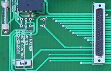
- Remote port for Remote Control Technologies and Rain Master.
- Fused 24vac power for external devises and remotes.
- Screw-driverless terminal blocks.
- Color coded wire harnesses.
- Optional Lightning protection in the UICL series.
Installation, wiring, and feature operating instructions:
- Circuit board mounting.
- Layout the UIC board in the desired location using the board itself or the enclosed drill template.
- Secure the drill template to the mounting surface using tape, then center punch each hole for drilling. Drill each hole with a 9/32 drill bit.
- From the back side of mounting surface, feed a ¼ x ½ screw with lock washer through hole and thread on corresponding stand off, but do not tighten. Do this for each hole.
- Place the circuit board on top of all the standoffs and align standoffs to the corresponding holes in the circuit board.
- Once all the holes are aligned, thread ¼ x ½ screws through circuit board into standoffs and tighten.
- Tighten all screws from the back side of the mounting surface.
- Master Valve Isolation Relay.
 P10
P10 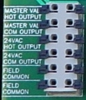 P1
P1
- Single Controller Operation
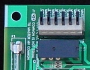
- Connect master valve or pump start output from controller to the Master MV Hot terminal of P10 of the UIC board. (P10 is 6 position terminal block located at the lower left corner of the UIC board.) Connect master valve or pump start output common output (this may be the field output common) from controller to the Master MV Com terminal of P10 of the UIC board.
- Connect the Hot lead from a master valve or pump start relay in field to the Master Valve Hot Output terminal of P1. Connect the Common lead from the master valve or pump start relay in field to the Master Valve Com Output terminal of P1. (P1 is located at the bottom of the UIC circuit board.)
- Master Slave Configurations
- Wire Master Controller as stated above in (a. step i.).
- Connect the Slave master valve hot output from the controller to the Slave MV Hot terminal of P10. Connect the Slave master valve common output from the controller to the Slave MV Com terminal of P10.
- Connect the master valve or pump start relay in the field as stated above in (a. step ii.).
- 24vac for external power and/or remote receiver.
- If there is not an obvious 24vac and common outputs on the controllers output board (as in the Rain Bird Esp-MC series controllers), then follow the instructions below in step b. Otherwise connect from the controllers 24vac output to the terminal labeled Master 24vac of P10. Connect the controller's common to the terminal labeled Master Common of P10. Note: If connecting this board to a Rain Master Sentar, Sentar II, Hawk, or Eagle use only the Rain Master remote port that is in its face plate. Rev A boards will not support powering up the remote port.
- Using a volt ohm meter set to ohms and with the 24vac transformer disconnected, measure the resistance between the common output of the controller to both of the 24vac transformer inputs. The 24vac input which measures zero ohms to the common is electrically equal to the common output. The other 24vac input is the 24vac Hot.
- Splice into the 24vac Hot wire or jumper from that input terminal of the controller and connect it to the Master 24vac terminal of P10.
- Connect a wire from the controller's common output to the Master Common terminal of P10.
- Verify proper wiring by measuring the resistance from the 24vac Common terminal of P1 to the common output of the controller, and from the 24vac Hot terminal of P1 to the 24vac hot input of the controller. Once the controller is powered up then an AC voltage test could be performed to verify continuous 24vac output at/between P1 terminals 24vac Hot and 24vac Common.
- Remote Port and Remote Selector Switch.
- Determine which remote is going to be used with this IC board.
- Move Remote Selector Switch (SW1) to desired remote setting.
- Make sure the power switch on the remote is in the OFF position.
- Make cable connections to remote and remote port(s) of IC board.
- Switch ON remote power switch and operate remote as desired.
- Caution: Do not switch selector switch from one position to another with the remote connected to the UIC board as this will damage the remote!
- Screw-driverless terminal blocks. (Reference pictures of P1 and P10.)
- Terminals P1-P7 can hold 12 gage and smaller wires. To insert solid conductor wires, strip wires approximately 3/8 then simply push the wire into the terminal slot. Each terminal position has the capacity for two wires. If using stranded wire you may need to press down the black lever either with your finger or a small screwdriver in order to properly seat the wire in the terminal slot. To remove the wire, press down the black lever and pull the wire out.
- Terminal P10 can hold 14 gage and smaller wires. To insert either solid or stranded conductor wires, lift the black lever, push in the wire, then push down the black lever so it snaps into place. To remove the wire, lift the black lever and remove the wire.
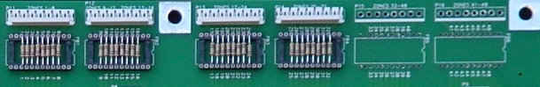
- Color Coded Wire Harnesses use the standard color to number coding scheme. The chart below shows how each color wire corresponds with its particular output.
| P11 | P12 | P13 | P14 | P15 | P16 | |
| Brown | 1 | 9 | 17 | 25 | 33 | 41 |
| Red | 2 | 10 | 18 | 26 | 34 | 42 |
| Orange | 3 | 11 | 19 | 27 | 35 | 43 |
| Yellow | 4 | 12 | 20 | 28 | 36 | 44 |
| Green | 5 | 13 | 21 | 29 | 37 | 45 |
| Blue | 6 | 14 | 22 | 30 | 38 | 46 |
| Violet | 7 | 15 | 23 | 31 | 39 | 47 |
|
Grey |
8 | 16 | 24 | 32 | 40 | 48 |
- UICL series, UIC board with Lightning Protection.
- The lightning protection devises on the UICL series boards will auto-reset, provided they are not damaged, with the exception of the resistive fuses located in the sockets on the left side of the board.
- To test the fuses, use a volt ohm meter. Each fuse will measure 1 ohm +/- 5%. Any other reading indicates a bad fuse. Indicators of a bad fuse are a zone which does not operate, a zone that does not fully operate, or visible discoloration or physical damage to the fuse.
- Each fuse is user replaceable. If a fuse is determined to be bad, simply pull out the bad fuse and replace it with a good one (this may require the use of a set of needle nose pliers). Additional fuse packs can be purchased from Control Tech USA, Inc. as part number CTU-FP. One CTU-FP should come with your board.
- Having a properly installed and operating earth grounding system is vital to the operation of the UICL's lightning protection devises. Control Tech USA, Inc. requires the grounding system to measure 10 ohms or less but preferably 5 ohms or less. Control Tech USA, Inc. has as part of its product line an excellent earth grounding kit and an earth ground resistance meter. Regardless of what type of grounding system used, it must be connected to the ground lug located at the bottom of the UICL board. It is best to use 6-10 gage solid conductor wire to connect the grounding system to the ground lug, and the shorter and straighter the wire the better.
There may be some unusual circumstances arise in some installations. If you need technical assistance please do not hesitate to contact us. Control Tech USA, Inc. representatives are available M-F from 8am to 4:30pm MST at (303) 814-0307 or 24 hour fax (303) 814-3719 or e-mail sales@controltechusa.com.